 Sulzer 2-pump controller PC 242
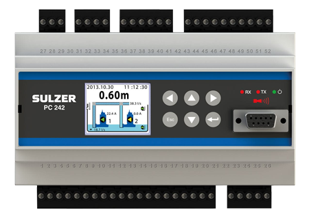
The PC 242 is a 2 pump controller designed mainly to be used in municipal wastewater pumping stations of either gravitation or pressurised type. It has many advanced features to minimise the costs in the pumping station throughout the whole life-cycle.The controller comes with graphical display to have a full user interface to fit in budget applications.
The level sensing in the pit may be done using either float switches or 4-20 mA sensor. Viewing of alarms, manual control of pumps and changing of settings etc. can be made locally via the graphical user interface. It can also be done via the configuration software AquaProg at a PC, connected directly to the local service port or remotely via e.g. modem.
Settings are password protected in two levels to avoid unauthorised or accidental changes. AquaProg software can be used for backing up the controllers settings on the hard disc, download alarms, events and historical data.
Features
- Advanced control of 2 pumps
- Communication via GPRS, GSM, tele modem or cable
- Logging of analogue signals, digital signals and alarms
- Level sensing by 4-20 mA sensor or float switches
- Mixer/flush valve control
- Pump capacity calculation and alarm
- Overflow measurement
- IN-rail mounted
Following values are accumulated and stored
- Pump start count
- Pump run time
- Overflow count
- Overflow time
- Overflow volume
- Pumped volume
- Energy/rain
CE
PC 242 fulfill following council directives and generic standards:
- 89/336/EEC relating to electromagnetic compability (EMC)
- EN 50 081-1:1992 Emission.
- EN 50 082-2:1995 Immunity.
- 72/23/EEC relating to safety requirements (LVD) EN 61 010- 1:1993
Functions
- Pump stop after max runtime setting.
- Pump run confirmation via motor current or contactor feedback
- Cyclic pump motion timer
- Emergency pump run timer on high float
- Overflow calculation and monitoring
- Pulse frequency to analogue, value conversion (energy/rain/inputs)
- Alarm dial-up
- GSM/SMS alarms
- GPRS modem support
- Modbus & Comli communication protocol
- Data logger 8 analogue channels 1-60 minute/sample: Level, motor current P1/P2, inflow/outflow, pressure, motor temperature (Pt 100) P1/P2,calculated energy/rain
- Data logger digital: Pump 1/2 on/off, alarms on/off/acknowledged
- SW clock for time and date. Must be set after each power up
- Inflow calculation
- Outflow calculation
- Personell alarm
Analogue inputs
- 2-wire level sensor 4-20 mA
- Current transformer P1 4-20 mA
- Current transormer P2 4-20 mA
- Pressure sensor for conditional pump blocking in pressurized systems (4-20 mA)
Digital outputs (potential free contacts)
- Pump control P1
- Pump control P2
- Common alarm output
- Mixer control/cleaning control/drain pump controlMotor protector reset/pump fail P1
- Motor protector reset/pump fail P2
- Reversing
- Alarm outputs
Telemetry interface
- 1 RS 232 port connects to modem, radio or other serial communication carrier
- 1 RS 232 service port
- Support for register and IO cross reference table
- Comli or ModBus RTU/TCP
Digital inputs
- High level float
- Overflow sensor
- Start float/run confirmation P1
- Start float/run confirmation P2
- Stop float (common)/ low level float (blocks pumping)
- Motor protector P1
- Motor protector P2
- Manual start of pump 1
- Manual start of pump 2
- P1 not in auto/pump fail
- P2 not in auto/pump fail
- Energy or rain meter 1
- Energy or rain meter 2
- Alarm reset
- Alarm input (free text)
Technical specifications
| Ambient operating temperature |
-20 to +70ºC |
| Ambient storage temperature |
-30 to +80 °C |
| Degree of protection |
IP20 |
| Housing material |
PPO and PC |
| Mounting |
DIN-rail 35mm |
| Humidity |
0-95% RH non condensing |
| Dimensions (HxWxD) |
86x160x60 mm
3.39x6.30x2.36 inch
|
| Power supply |
9-34 VDC |
| Power consumption |
150 mA, average at 24 VDC |
| Max load DO relays |
250 VAC 4 A, max 100 VA resistive load |
| Digital input voltage |
5-34 VDC |
| Digital input resistance |
10 k ohm |
| Analogue sensor |
4-20 mA |
| Analogue input resistance |
Level sensor 16 bits |
| Temperature sensor |
Other Al 10 bits |
| Leakage sensor |
RS 232 |
| Analogue input resolution |
15 days at 8 channels, 1 min interval
|
| Digital signals |
4096 events |