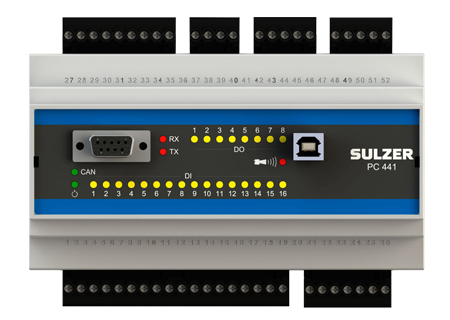
 Sulzer 1-4-pump controller PC 441
The PC 441 is a 1 to 4 pump monitor and controller, designed mainly to be used in municipal wastewater pumping stations. PC 441 can also be used as a standalone monitoring unit. It has many advanced features to minimize the operational costs and increase the availabil-ity of the pumping station throughout the whole life-cycle.The controller can be connected to a graphical display, CA 511, to have a full user interface with possibilities to view and set all param-eters. For level sensing, hydrostatic or other devices with 4 to 20 mA signal can be connected, also the use of float switches is possible.Viewing of alarms, manual control of pumps and changing of set-tings etc. can be made locally via the graphical user interface. It can also be done via the configuration software AquaProg in a PC, con-nected directly to the local service port or remotely via e.g. modem. Settings are password protected in two levels to avoid unauthorized or accidental changes.
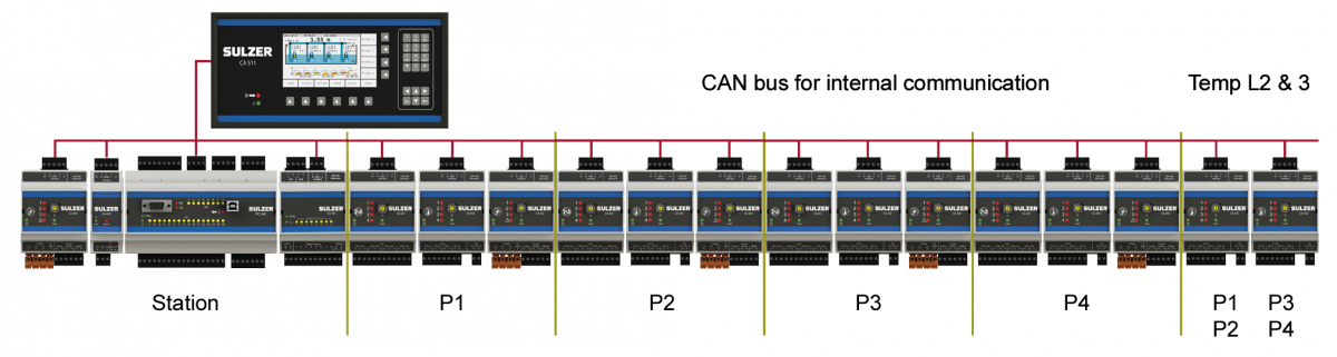
For more advanced functionality there are 5 additional units that can be connected:
CA 441, Moisture monitoring module for connection of 4 pumps with combined alarms or 3 separate alarms using one unit per pump.
CA 442, Temperature monitoring module for connection of 4 pumps with combined alarms or 3 separate alarms using one unit per pump and a separate mA input for a vibration sensor.
CA 443, Motor and supply power monitoring module for a complete station and/or one per pump.
CA 622, RS 485 communication module for the Sulzer PC 441 concept. The unit is connected to the system via CAN bus and is fitted with a RS 485 communication port for communication with peripheral products as VFD’s, Soft starters, Energy meters etc. The unit is powered via the can-bus.
CA 781, Output expansion module fitted with 8 nb of digital outputs and 2 nb of analog outputs. The unit needs power supply via an external source.
Features
- Advanced monitoring of 1-4 pumps
- Advanced control of 1-4 pumps
- Communication via GPRS, GSM, tele modem or cable
- Logging of analogue signals, digital signals and alarms
- Level sensing by 4-20 mA sensor or float switches
- Mixer/flush valve control
- Advanced pump capacity and outflow calculation with alarm handling
- Overflow measurement
- DIN-rail mounted
Following values are accumulated and stored
- Pump start count
- Pump run time
- Overflow count
- Overflow time
- Overflow volume
- Pumped volume
- Energy/rain
- Flow
- kWh/m3 or kWh/Mgal
Pumps control function
- Variable start / stop levels per day and night in a week
- Alternative stop level
- Empty pump station before “rush hour”
- Start / Stop based on speed of level change
- Ratio start of pumps
- Random start levels
- Smart VFD control
- Auto reverse of pump
- Max runtime check
- Cyclic motion timer
- Remote blocking of pump via communication
Sump monitoring function
- Max number of pumps running
- Mixer control logic
- Flush valve or sprinkler control logic
- Drain pump monitoring
- Level signal check via high level float
- Timer based back-up run of pump via high level float
- Sump level indication calculated from sump bottom or sea level
In- / outflow, pump capacity and overflow calculation!
- Calculate the inflow using level change per time unit times surface area
- Calculate the pump capacity every time one pump runs by itself
- Pump & system curves can be entered for more exact calculation
- Outflow calculation compensation for rpm
- Overflow calculation based on level signal with trigg of measurement. Overflow = he1c1 + he2c2 [m3/s]Communication interface
- 1 RS 232 port connects to modem, radio or other serial communication carrier.
- 1 USB service port
- RS-232 service port
- Comli or ModBus RTU/TCP
- Register & IO cross reference table
Other functions
- Pulse frequency to analogue, value conversion (energy/rain/flow inputs)
- Alarm dial-up
- GSM/SMS alarms
- GPRS modem support
- Modbus & Comli communication protocol
- Data logger 16 analogue channels 1-60 minute/sample: Level, motor current P1/P4, inflow/outflow, pressure, motor and bearing temperature (Pt 100) P1/P4, calculated energy/rain/flow
- Data logger digital: Pump 1/4 on/off, alarms on/off/acknowledged
- RT clock (Real Time) for time and date. 6 h internal back-up of RT clock.
Technical specifications
| Ambient operating temperature |
-20 to +50ºC |
| Ambient storage temperature |
-30 to +80 °C |
| Degree of protection |
IP20 |
| Housing material |
PPO and PC |
| Mounting |
DIN-rail 35mm |
| Humidity |
0-95% RH non condensing |
| Dimensions (HxWxD) |
86x160x60 mm
3.39x6.30x2.36 inch
|
| Power supply |
9-34 VDC |
| Power consumption |
< 5.0 W (excluding DO load) |
| Max load DO relays |
8 DO. Positive logic. Sourcing from power supply 1A/output.Max total current for all 8 outputs together is 4 A. |
| Digital inputs / Input resistance / Input voltage |
16 DI. Positive logic 10 kohm 5-34 V. Trig level ~ 4 V |
| Max pulse rate digital in 13-16 |
500 Hz (pulse channels) |
| Analogue outputs / Max load / Resolution / Current limit |
2 AO. 0/4-20 mA Sourcing from power supply 500 ohm@12 V,1100 ohm@24 V 15 bits 0.5 uA-22 mA |
| Analogue inputs / Input resistance / Resolution |
5 AI. 0/4-20 mA 136 ohm.PTC protected AI1 : 15 bits (level sensor). AI2-5 : 10 bits |
| Communication ports |
1 RS232 Service port, 1 RS232 port for telemetry interface (modem), 1 USB2 Service port |
| Field Bus (to CA 511/CA 441........) |
1 CAN Port. Max current load 350 mA |
| Data memory (logger) |
|
| Analogue signals |
15 days with at 16 channels and 1 min interval |
| Digital signals and alarms |
4096 events |