 Sulzer Equipment controller ЕC 531
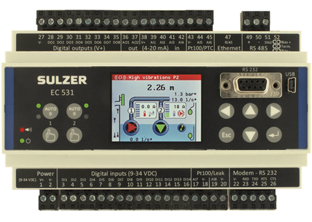
The equipment controller EC 531 is an all-in-one unit for monitor-ing and control of one or two pumps. It is designated primarily for municipal pumping stations. The software included in the EC 531 is a further development of the PC 441 advanced surveillance systems.
Viewing of alarms, manual control of pumps and changing of set-tings etc. can be made locally via the graphical user interface. It can also be done via the configuration software AquaProg at a PC, con-nected directly to the local service port or remotely via e.g. modem.Settings are password protected in two levels to avoid unauthorized or accidental changes.
AquaProg software can be used for backing up the controllers set-tings on the hard disc, download alarms, events and historical data.
Key control parameters
- Level set-point, including time delays
- Speed of level change
- Random start levels
- Tariff control
- Maximum runtime
- VFD control logic, including flow calculation, day set points, night set-points and adjustable pump reversal speed
- BEP (Best Efficiency Point)
Data communication
- Communication via Modbus (RTU / TCP) protocol with other telemetry or SCADA systems
- I/O and register cross-reference tables for efficient communication setup
- Ethernet communication support
Communication interface
- Communication port RS 232, connect to modem, radio or other serial communication carrier
- Service port for PC connection, RS 232 and USB
- RS 485 to VFD, Soft starters and Energy Meter
- Ethernet by RJ45 plug
Operator panel
The built-in operator panel with graphical display and keypad ensures
easy configuration and operation of the EC 531. It allows the
operator to see pump status at a glance. Graphical symbols (high
temperature, leakage, electric fault, vibration fault) will turn red when
an alarm is activated. Detailed information about the behavior of the
float controls is displayed in a separate view.
Data from the panel can be viewed or accessed in different formats:
alphanumeric characters or animated graphical symbols.
Functions
- Graphical operator panel
- Digital outputs (8)
- Analog outputs (2)
- Analog inputs (4)
- Temperature inputs PTC / Klixon / Pt100 (2)
- Com port for Modbus on TCP, RJ-45 Ethernet
- Com port for Modbus on RS 4858 Off - auto and forced start buttons
- Power indicator
- Alarm indicator
- Service port for PC connection, RS 232 and USB
- Com port for modem connection, RS 232
- Leakage sensor inputs or temp. inputs Pt100 (2)
- Digital inputs (14)
- Power connection 9-34 VDC
Analogue inputs
Four inputs, 2-wire 4-20mA:
- Pit level
- Motor current
- Outlet pressure
- Vibrations
- Xylem MiniCas Sim
- Outflow meter
- Motor temperature
- Free choice
Four inputs, 2-wire Analog temperature:
Four Analog inputs:
- four can be used as Pt100
- two can be used as PTC
- two can be used as leakage
Digital inputs
- Run indication
- Manual start
- Set manual
- Set auto
- Start float
- Pump failure
- Motor protector
- High motor temp. pump
- Leakage pump
- Stop float
- Low level float
- Overflow sensor
- High level float
- Start float drain pump
- Local mode
- Alarm reset
- Power fail
- Pulse channel 1-4
- Block PID controller
- Alarm input (free text)
- Block operation
- Leakage mixer-drain pump
- High temp mixer-drain p.
Analog outputs
- Pit level
- Pit in/outflow
- Pit overflow
- Pulse channel 1-4
- PID control output
- Data register 16 or 32 bits
- Set frequency P1 or P2
Digital outputs
- Pump control P1
- Pump control P2
- Reset motor protector
- Pump fail
- Not enough pumps available
- One pump fail
- Mixer control
- Drain pump control
- Cleaner control
- Modem control
- Remote control
- Personnel alarm
- High level
- Alarm alert
- Not acknowledge alarms
- Active alarm
- Pump reversing
- Logic IO
- Data register setpoint
- External reset alert
Integrated amplifiers
- Selectable 4 Pt100 inputs or
- 2 Leakage and 2 PTC/Pt100 inputs CE
CE
EC 531 fulfill following European council directives and generic standards:
- 2014/30/EU electromagnetic compatibility (EMC) EN 61326-1:2013
- 2011/65/EU restriction of hazardous substances in electrical and electronic equipment (RoHS 2)
Technical specifications
| Ambient operating temperature |
-20 to +50ºC |
| Ambient storage temperature |
-30 to +80 °C |
| Degree of protection |
IP20, NEMA: type 1 |
| Housing material |
PPO, PC, UL 94 V-0 |
| Mounting |
DIN-rail 35mm (1.378" W) |
| Humidity |
0-95% RH non condensing |
| Dimensions (HxWxD) |
86x160x60 mm
3.39x6.30x2.36 inch
|
| Power supply |
9-34 VDC SELV or Class 2 |
| Power consumption |
< 5.0 W (without output load) |
| Digital Outputs, properties |
8 pcs. configurable logic, max load 1A/output, < 34 VDC (sourcing from power supply), only sourcing -no drain, max load 8 outputs = 4 A. |
| Digital Input, properties and voltage |
14 pcs., max 1 kHz (pulse channels), trig level ~4 VDC, 0-34 VDC |
| Digital Input resistance |
10 k ohm |
| Analog Inputs |
4 channels 4-20mA and 4 channels configurable Pt100/PTC/Leakage |
| Analog Input resolution (4-20mA) |
AI1: 15 bits, AI2-4: 10 bits |
| Telemetry interface |
Ethernet and RS 232 |
| Data logger: |
|
Analog signals
Digital signals and alarms
Crash log |
15 days at 16 channels, 1 min interval
4096 events
8 logs, 16 parameters, 90 min before and 45 after crash log initiates, 1 sec. res
|
| Communication |
1 USB Service port (USB mini-b)
1 RS 232 Service port (9p D-SUB F)
1 RS 232 port for telemetry interface (modem) (screw terminals)
1 RS 485 2-wire (galvanic isolated) communication to VFD, soft starters and energy meter (screw terminals)
1 TCP/IP Ethernet for telemetry (RJ45) |