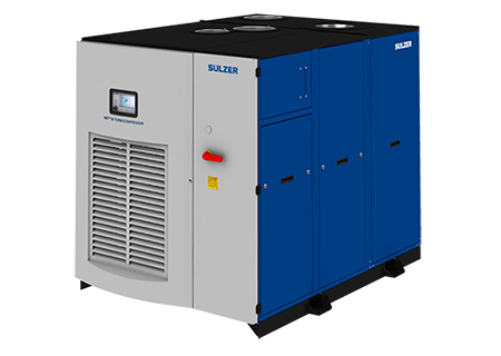
Sulzer turbocompressor HST 30
A highly efficient and reliable single-stage centrifugal compressor for the provision of oil-free low-pressure air.
Construction
- High-speed electric motor
- Air end
- Variable frequency drive
- Active magnetic bearings
- Blow-off valve
- Acoustic enclosure
- Integrated components
High speed electric motor
A horizontally mounted high-frequency electric motor for variable speed operation. The motor is air-cooled by an integrated shaft mounted fan and the windings are protected by Pt100-sensors monitored by the local control system.
Air end
The impeller has been designed to optimize performance and is machined from a solid piece of high-strength aluminum alloy. The volute and other main components are made from cast aluminum. A non-contact seal between air-end and motor minimizes losses to maintain high efficiency.
Variable frequency drive
Flow control is provided by a built-in variable frequency drive which also accommodates variations in outlet pressure and ambient inlet conditions. The variable frequency drive’s soft-start facility eliminates peak starting currents.
Active magnetic bearings
Two radial bearings and two axial bearings support the rotor. The magnetic bearing controller uses data provided by multiple sensors to continuously manage the position of the rotor.
Compressor Control:
The built-in local Human-Machine-Interface (HMI) provides control and monitoring for the safe and efficient operation of the machine. Flow may be controlled directly by the operator, or alternatively, the turbocompressor can follow a given reference value. The local HMI uses a color touch screen to provide access to the operator.
Analog and digital control and monitoring connections are built in. Fieldbus connections such as Profibus, Profinet, Modbus RTU, Modbus TCP, and EtherNet/IP are available as options.
A secure connection facilitating service and monitoring can be ordered as an option.
Options
Various options for handling special requirements regarding e.g. temperature, dusty environments and locations with high moisture can be selected.
Accessories
Required accessories for installation such as flexible joints, valves, silencers, and air filters are available from Sulzer.
Certification and Standards
The product is CE certified and complies with:
- Machinery Directive (MD) 2006/42/EC
- Electromagnetic Compatibility (EMCD) 2014/30/EU
The product is designed and manufactured in accordance with EN 61800-3 standard and intended for use in second environment locations, e.g. in industrial area
Performance Testing
Compressor performance tests are performed on every machine manufactured and certificates issued to confirm compliance. The tests are carried out at the Sulzer factory test facility. Performance is guaranteed with a manufacturing tolerance of ± 2% and a measurement tolerance according to ISO 5389. Optionally tests can be performed in full accordance with ISO 5389 and/or witnessed by the client.
Installation Conditions1
| Altitude |
|
| Maximum altitude |
2500 m above sea level2 |
| Air quality |
|
| Permitted chemical vapor |
IEC 60721-3-3 class 3C3 |
| Ambient conditions |
|
| Ambient temperature range1 |
Min. -10 °C, max. +45 °C |
| Ambient relative humidity |
< 95 %, non-condensing, non-corrosive, no dripping water |
| Inlet conditions |
|
| Air temperature range for inlet process air |
Min. -30 °C, max. +50 °C |
1 Sulzer may approve applications outside these criteria.
2 2000 m above sea level for 690 V compressors.
Compressor data
|
HST 30
|
-36-1-190
|
-36-1-250
|
-36-1-300
|
-46-1-190
|
-46-1-250
|
-46-1-300
|
|
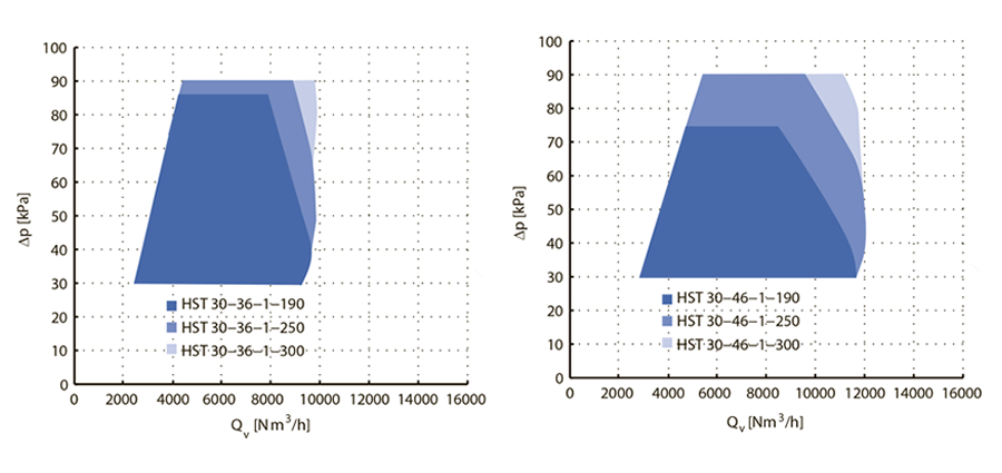
Air flow range [Nm3/h]
|
2000-9000
|
2500-9600
|
2500-9800
|
3000-11500
|
3000-11800
|
3000-11800
|
|
Pressure rise [kPa]
|
30-85
|
30-90
|
30-90
|
30-75
|
30-90
|
30-90 |
|
Max noise level [dB]
|
73
|
72
|
62
|
73
|
72
|
72 |
|
Input power [kW]
|
190
|
250
|
300
|
190
|
250
|
300 |
|
Power supply [V]
|
380-690
|
380-690
|
380-690
|
380-690
|
380-690
|
380-690 |
|
Input power frequency [Hz]
|
50/60 |
50/60 |
50/60 |
50/60 |
50/60 |
50/60 |
|
Max. current (400V) [A]1
|
301
|
397
|
476
|
301
|
397
|
476 |
|
Max. current (500V) [A]1
|
241
|
317
|
190
|
241
|
190
|
381 |
|
Max. current (690V) [A]1
|
315
|
230
|
138
|
175
|
138
|
276 |
|
Cable size (400V) [mm2]
|
3x185+95
|
2x(3x120+70)
|
2x(3x150+70)
|
3x185+95
|
2x(3x120+70)
|
2x(3x150+70) |
|
Cable size (500V) [mm2]
|
3x120+70
|
3x185+95
|
2x(3x120+70)
|
3x120+70
|
3x185+95
|
2x(3x120+70) |
|
Cable size (600V) [mm2]
|
3x70+35
|
3x120+70
|
3x150+70
|
3x70+35
|
3x120+70
|
3x150+70 |
|
Fuse size (400V) [A]
|
400
|
500
|
630
|
400
|
500
|
630 |
|
Fuse size (500V) [A]
|
315
|
400
|
500
|
315
|
400
|
500 |
|
Fuse size (600V) [A]
|
200 |
315 |
315 |
200 |
315 |
315 |
|
Weight [kg]
|
1570 |
1570-1630 |
1600 |
1600-1660 |
1630-1690 |
1630-1690 |
1The maximum input current is calculated using the nominal voltage.The cable and fuse sizes are recommendations and based on the supply current and cables rated to 70 °C.